Packet Network TrainingTable of Contents
Purpose of a Networkcommunicate without interfering with or being interfered with by local access hardware that is optimized for passing data, rather than optimized for user stations. "Users", "Hosts" and "Services" on a NetworkKeyboard-to-KeyboardKeyboard to Keyboard is just what it sounds like. Two individual stations communicating with one another from your keyboard to the other guys keyboard. You might think of this as a QSO, or a Rag Chew.Keyboard-to-HostKeyboard to Host is when you connect to a Host on the network from your home station. This Host may be a.....BBS'sConference BridgesFile TransfersAccess to WL2K TelPac NodesVarious "Styles" of Packet NetworksDigipeatingKA-nodeNetROM (Knet/TheNet/X1J4)NetROM was a networking protocol developed by Software-2000 in the 1980's. NetROM was a bold step forward because it allowed a node to communicate with its neighbor nodes and share the route tables that they had each discovered or shared with their neighbors. This meant that nodes hundreds of miles away were known to your local node. And the route to get you from your local node to the distant node was automatic.Automatic route discovery and automatic routing of traffic greatly simplified the Packet networks from the users perspective. S/he no longer had to manually crawl his way across the country, but could now simply list the nodes known to his local node or any node along the desired path to see what distant places could be reached. It was not uncommon for a user in San Diego California to use the NetROM networks to work his way all the way to Washington D.C.! The NetROM protocol was originally a ROM that had to be burned with certain key information (such as station callsign and nodename) and then placed into a TNC-2 "clone" TNC. Hence the name - Net ROM. It was later implemented within the software of several Bulletin Board programs and into the various xNOS programs such as JNOS and TNOS. .....NetROM Stacks........ ........K-net....... .... TheNet.....
.....X1J4.....
...which carries us into the TCP/IP networks....
TCP/IPTCP/IP, or Transmission Control Protocol / Internet Protocol, is the basis of todays Internet. TCP/IP includes a wide "suite" of other protocols such as TELNET (Terminal Session), ICMP (Ping), SMTP (E-Mail), FTP (File Transfer), FINGER, NTP (Time), and others.Phil Karn KA9Q wrote the first implementation of TCP/IP for Packet Radio called "NET". Very quickly other software contributors added additional features and functions to the code set, and it later became known as "NOS", or Network Operating System. One of those flavors of NOS was produced by WG7J who called his release JNOS. JNOS is still supported today by Maiko Langalear VK???? in British Columbia. .....what JNOS can do..... ....how JNOS is networked together...... ......how JNOS can be configured as a HamGate....
==========================================================
In a flat WAN a station in each of two neighboring LANs may communicate beyond their radio horizons much as when using a voice repeater. Connections are made between the nodes using digipeating (as in APRS), or node-to-node connections (as in SEDAN). The latter facilitates data transfers using temporary store-and-forward of the data eliminating the need for end-to-end digipeating acknowledgement. Where sufficient stations are strategically located, and conditions amenable, connections may be made over several hundred miles in tens of seconds. Since all nodes are on the same frequency, they must timeshare the channel. Two neighbor nodes may keep many others tied up as the protocol only permits one station within the broad radio horizon to use the channel at one time. The use of tall towers increases the occurrence of interference between alternate neighbor stations. In Florida skip due to ducting on vhf/uhf often aggravates this situation, reducing the throughput rate on sections of a flat WAN. The occurrence of "hidden transmitters" (stations which are not seen by all nodes) increases as the number of nodes increases and as the range of any single node increases with antenna height or unusual propagation. Therefore, where a LAN is on the same frequency as the flat WAN, (i.e., all user stations are on the WAN frequency, along with the network NODES), the network may become loaded with just a few stations passing information. (Six stations in the Sanford, FL area tested the conference mode on the local SEDAN node on 145.770 after dark. Within five minutes over half of the SEDAN network in Florida was tied up. Yet, all the stations on the conference were only connected to the local SEDAN node.) Most WANs are not equipped to handle large data file (message) transfers. Neither the APRS nor the SEDAN networks accommodate large file transfers, and specifically discourage the use of BBS-to-BBS transfers across the network. The layered network approach is designed to minimize, virtually eliminate, interference between adjacent LANs by (1) coordinating neighboring LANs on different frequencies, and (2) connecting between neighbor LANs on yet a third frequency. With proper coordination, channel timesharing is restricted to the LAN level, each LAN is independent, and transfers between LANs are transparent to all users. Antenna height and ERP are driven only by requirements to serve the LAN, and beams are used for point-to-point backbone transfers between LANs. This requires a greater number of packet nodes than a WAN to cover a wide area but, when taken to full fruition, provides excellent throughput on a 24/7 basis and is less susceptible to changing propagation conditions. The main purpose for the layered network in Florida is to move large message files from one location to another, primarily in support of emergency communications preparedness. The most efficient way to manage this is to use BBS-to-BBS transfers that are automated once configured. BBS protocols are efficient at managing transfers through a network. Because BBS transfers are generally not made on the LANs, keyboard QSOs on a LAN, user keyboard QSOs between LANs over the backbones, and BBS transfers between LANs over the backbones may be ongoing at the same time. This is ideal to support emergency operations in adjacent LANs (e.g. two adjacent counties), as neither LAN will interfere with the other, yet traffic flows freely between LANs over the backbone channels. The layered network in Florida employs switches using the ROSE or compatible FPAC network management. A typical network switch has three radio ports on three different frequencies. Each port requires a TNC, a radio, and an antenna. The 2M LAN is one port on a switch; the other two ports are backbones, each linking to a different neighboring switch. The switching functions between ports are managed by firmware or computer, totally transparent to users on the network. Local keyboard users on the LAN connect to users on another LAN through the switch which automatically routes to the destination over the backbone ports at higher speed. Network routing tables are established at each NODE and may be updated remotely. This facilitates routing between any two packet stations that have network access anywhere in the State. A connection is made by sending only three elements in a single command: target mycall, local switch call, and target node identifier. The network manages the connection across all network nodes totally transparent to the user. This automatic routing scheme is not compatible with that used by X1J-, TheNet, or KA nodes commonly employed on wide area flat networks in Florida.
===========================================
Flat vs Multi-Layer TopologiesSingle Frequency NetworkIn a network where there is a single frequency....single collision domain Hidden Transmitter problem
http://www.fadca.org/n0ia_5.html

LAYERED VS WIDE AREA (FLAT) PACKET NETWORKS

bud Thompson N0IA
n0ia@n0ia.#cenfl.fl.usa.noam
budt@cfl.rr.com

Flat wide area networks (WANs) utilize packet nodes all on the same frequency,
and placed on tall towers to extend the radio horizons so to minimize the numbe
r of nodes and thus the cost to cover a wide area. The tradeoff is that many of
 the stations can "see" each other resulting in undesirable channel sharing ove
r large portions of the network. A layered network uses different frequencies f
or local operations than for point-to-point links between local area networks (
LANs) to virtually eliminate channel sharing except at each LAN where sharing i
s manageable. Greater throughput on a 24/7 basis is more assured than on a WAN.
 The tradeoff is that a greater number of packet switches is required as the co
verage by each is not as broad.
Multi Frequency NetworkBy moving away from a single frequency, we introduce a new problem, and that is how do two stations in different networks reach one another?Layered Network - A layered network uses different frequencies for local operations than for backbone links between local area networks (LANS) to virtually eliminate channel sharing except at each LAN where sharing is manageable. Greater throughput on a 24/7 basis is more assured than on a flat network. The tradeoff is that a greater number of packet switches is required as the coverage by each is not as broad. Gateway NodesAs shown in the image, we have two networks on two different frequncies. We will call them the Blue Network and the Green Network. Obviously without some gateway between these two networks, there will be no way to make connections to stations in the other network.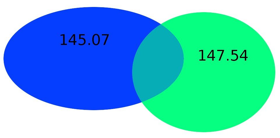
NetROM GatewaysEnter the NetROM Stack. The NetROM Stack is where two complete NetROM nodes, usually one on each of the networks we wish to gateway together, have their RS-232 serial ports connected together. As NetROM considers its serial port to just be another interface into the network, if we tie serial ports of multiple NetROM nodes together it is as if they all had a private (and very fast) radio link between them.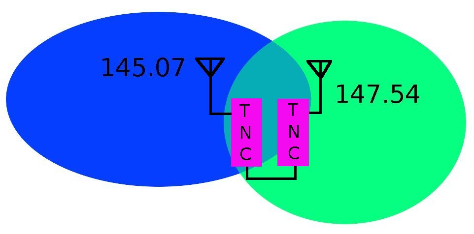 There is one caveat that must be followed should 3 or more nodes be
interconnected in this way. That is to diode block or diode OR
certain RS-232 signals with one another. This is to......
There is one caveat that must be followed should 3 or more nodes be
interconnected in this way. That is to diode block or diode OR
certain RS-232 signals with one another. This is to......
The following image shows the typical wiring of three NetROM nodes and how the serial port leads are disode ORed together. 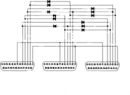
HamGate Gateways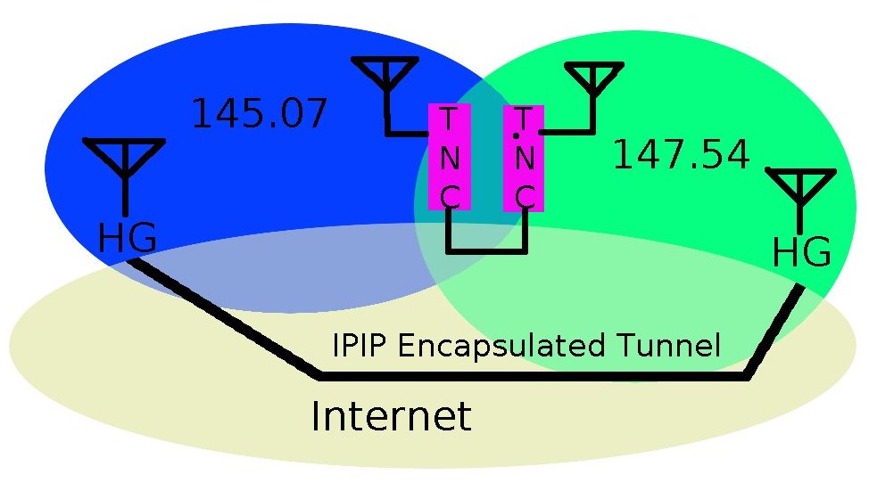
Homoginous NetworksWe can now bring into the fold distant networks that may be elsewhere in the State, or may be far distant - in another State or even in another Country. We will show that distant network as the Orange Network.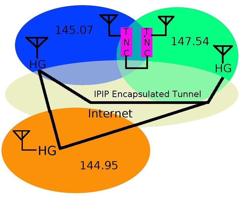 Because all the registered HamGates around the world contain the ENCAP.TXT
routing tables, they are fully meshed in a direct Peer to Peer
network.
Because all the registered HamGates around the world contain the ENCAP.TXT
routing tables, they are fully meshed in a direct Peer to Peer
network.
There being no heirarchy of routers between them, they only need that the
Internet have a working path between them to operate. The dependability
of the Internet's backbone networks is on the order of five nines,
or 99.999% dependability, the weakest link in this system is the last mile
between the HamGates' host site and its upstream ISP provider.
xxxxxxxxxxxx
|
 There are several solutions to this problem